I recently revised my how-to-download-the-USDA Standard Reference Food and Nutrition database for SR28. You can find the SR24 still on the site but the front page link now points at the current version.
CHAIR-LOC info page
In my previous posts here and here I have referred to product called Chair-Loc. This is is labeled on my bottle as “rosin triethanolamide”. My bottle was made by The Chair-Loc Company of Lakehurst, NJ.
I have not been able to find Chair-Loc in local stores. I found that it might be available at Contantines Wood Center. Either a 2oz bottle alone ($4.25) or a 3oz bottle in a kit with syringe and tips to inject the joint ($11.95). Also at Western Wood Doctor with similar but different pricing.
Google search and Amazon provide a number of false leads and alternatives.
Wonderlokking Tite Chair glue is a cyanoacrylate glue which may work well at repairing chairs. The problem is that is really is a glue. If you have to disassemble the chair to repair the wood, covering, or as a result of refinishing, the glue will stick to the wood fibers and tear them apart. My theory is that if you want to repair furniture, you want to do it with glues that fill, swell, tighten, but do not stick. CA glue is sticky, particularly if you get it on your fingers.
Behlin Swel-Lock (scroll to page 16) may work, I have not tried it. The MSDS says that it is dipropylene glycol. I see information on the web that antifreeze (ethylene glycol and diethylene glycol) is a traditional fix for loose ax handles. I have not used it and cannot comment on how well it works or how long it lasts.
Briwax ChaiRX is a self-crosslinking vinyl acrylic polymer emulsion. While the MSDS states that the emulsion contains a large amount of water, if, on drying, the vinyl acrylic polymer remains in the wood fibers and joint, the joint should remain tight some time. This may be the best replacement available today for my favorite chair repair.
Briwax MTD, a wood sweller for mortice and tenon joints appears to be similar and may work as well.
When I get time, I will update the links to Chair-Loc in other posts to point to this info page.
Building an Empire
My son’s girlfriend gave me a great Christmas gift.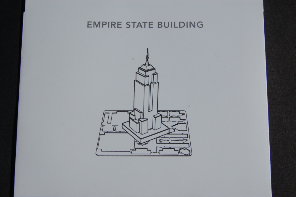
In one shot it satisfies my longing for metal-working, model making, real estate, architecture. WOW!
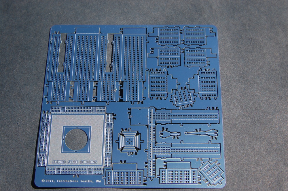
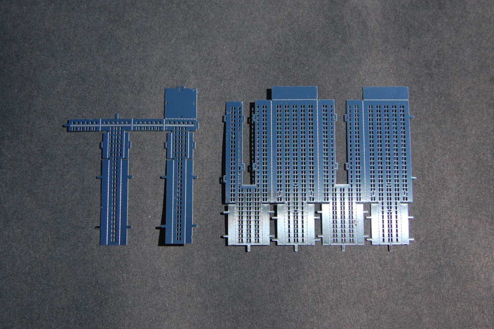
These laser-cut pieces of sheet metal can be re-arranged into actual models of things New York City, New York
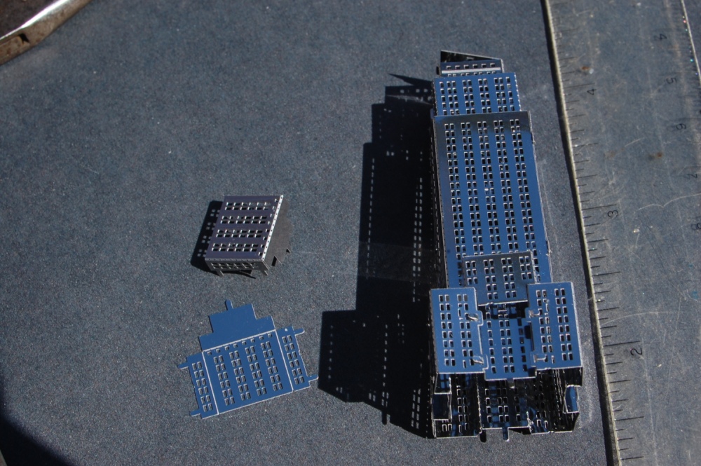
I previously put together the model of the Chrysler Building but have not yet posted the pictures. In this post, I will discuss the Empire State Building
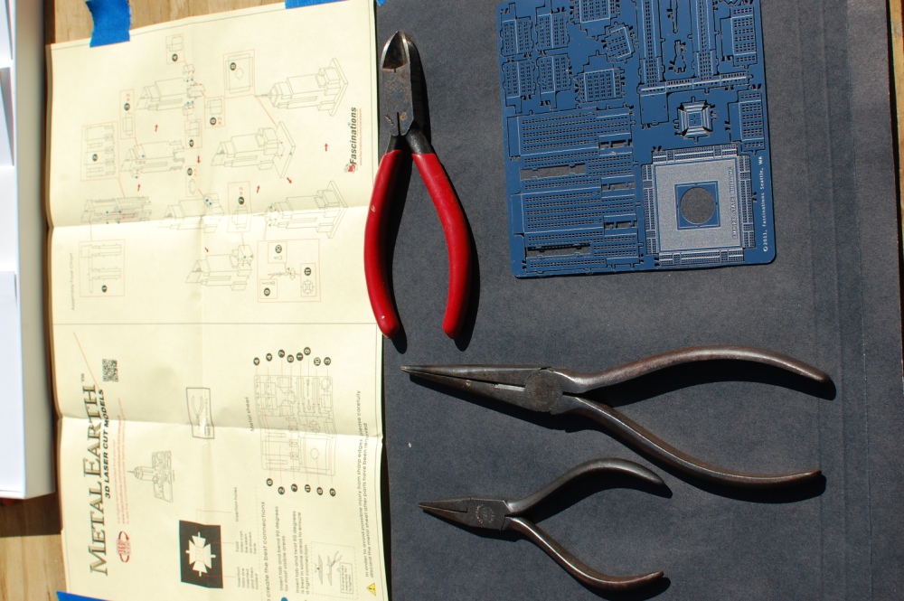
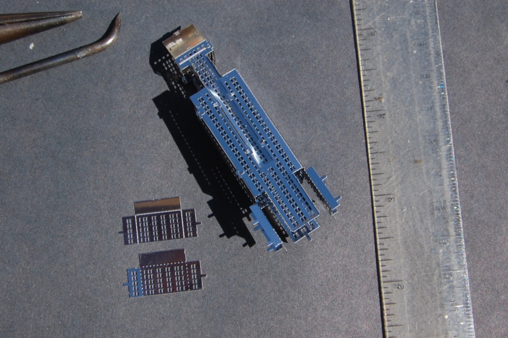
I have shown some of the tools that I used to assemble the Chrysler building but as always, experience teaches and I added a couple tools, tips, and techniques down the road. I tried to rotate the image so that the instructions were on top but it did not seem to take. If you buy the kits, you will get a separate instruction sheet for each model.
The diagonal cutters may be useful on the larger pieces that are anchored in three places to break the third point so the model piece can be rotated about the other pair of points to get it to separate. Be careful not accidentally flex or bend the individual pieces while removing them from the carrier flat sheet.
The pieces have folds. The dotted-line folds are “valley folds”. The solid line folds are “mountain folds”. Only make the folds as described by the directions. Making a fold too early may make a later assembly difficult.
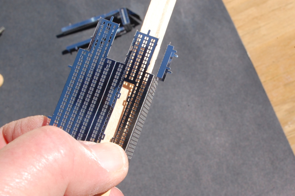
Visible joints are tab-thru-slot folded over. The hidden ones, mostly on the base, are tab-thru-slot twisted to tighten. The instruction sheet notes these with an icon dipicting the correct technique.
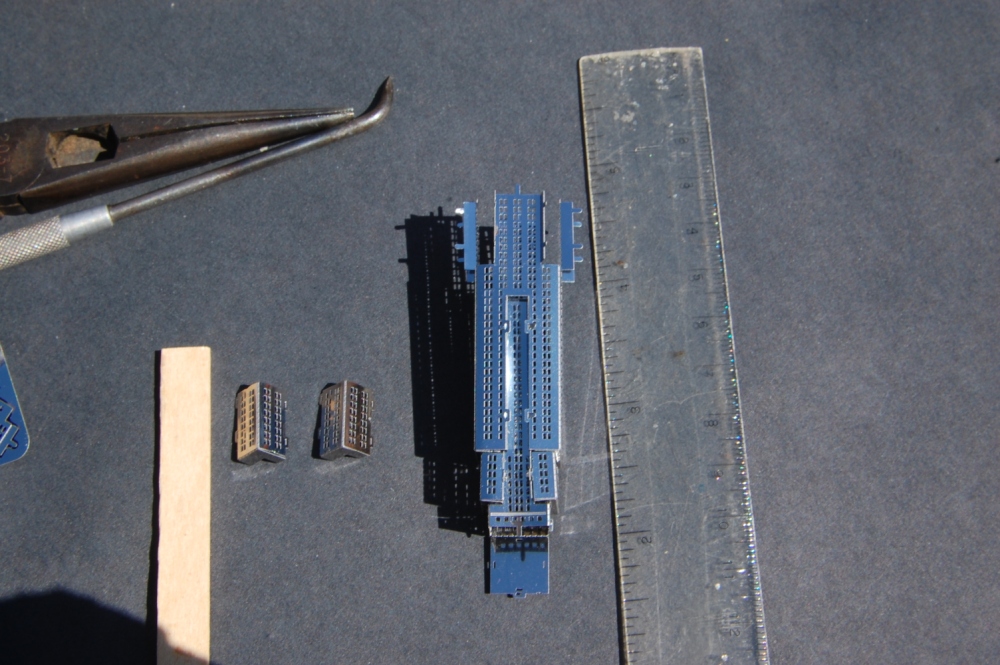
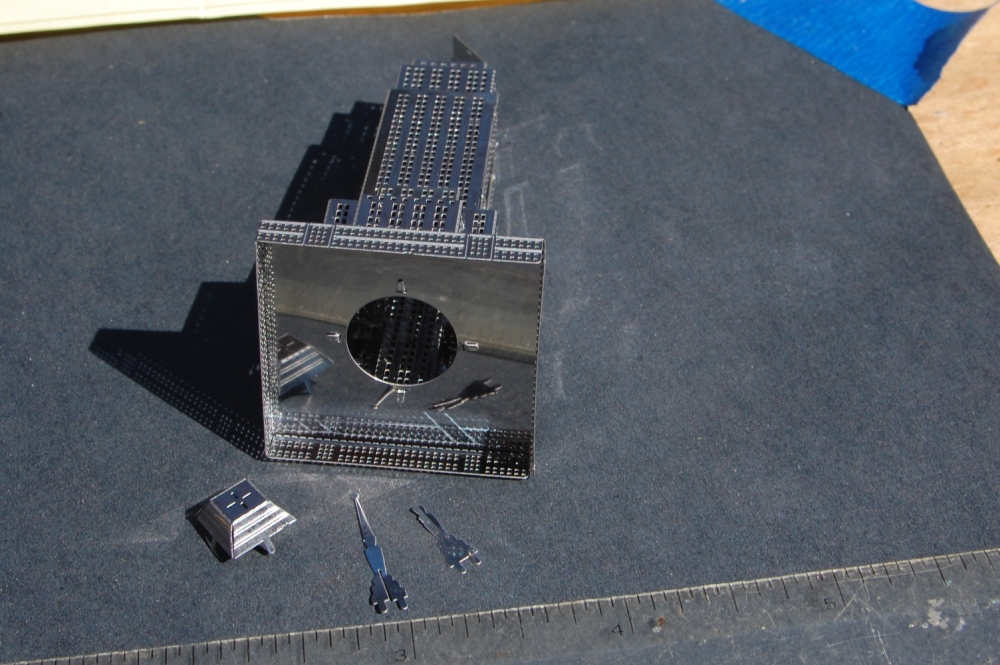
The architectural and visual interest of the Empire State Building comes from its intersecting solid volumes. To construct these from sheet metal makes the challenge of marrying two not-quite square folded sheets and getting all of the tabs to line up with all of the slots. I found that the Popsicle stick, a scribe, the needle-nose pliers and a lot of patience were all helpful.
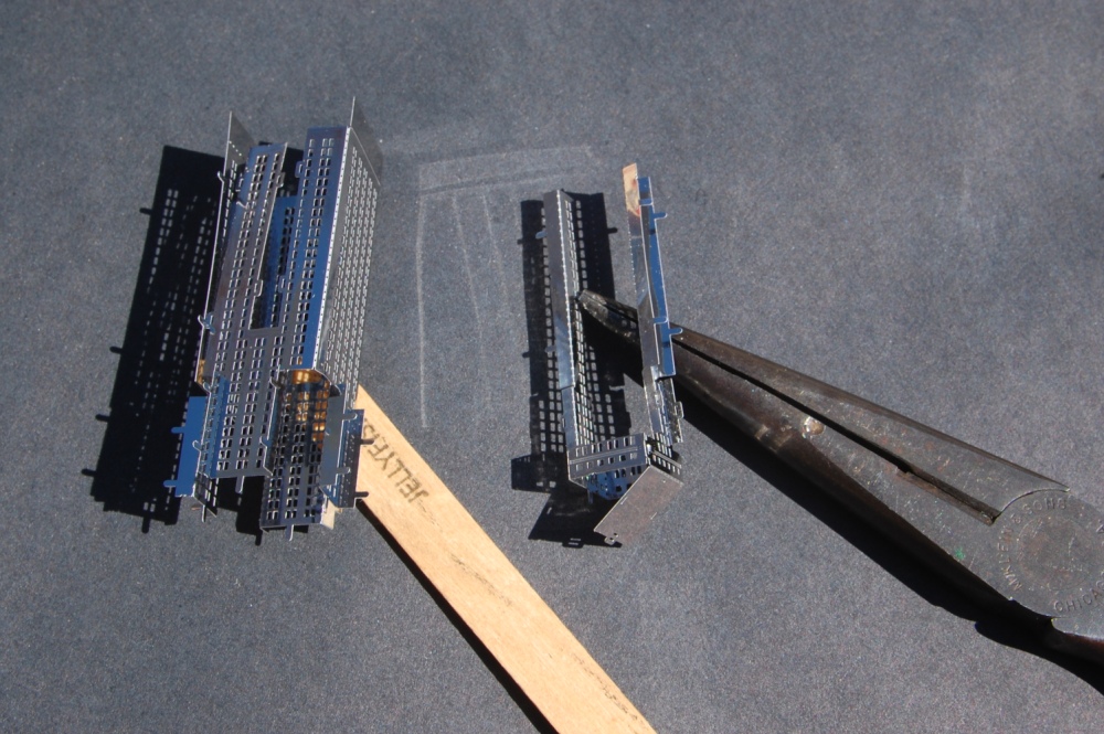
I realized as I was working that some of the longer folds were difficult to keep flat and square without a hard surface with a flat edge. I made a “brake” from a Popsicle stick that helped make the folds flat and square without distorting the adjacent surface. Cut one of the rounded ends off square with a hobby-knife or fine saw. You can also use this tool as a poker to flatten internal tabs or to flatten a surface that has been pushed in too far during assembly.
You may be able to see that I squeezed to hard and curved a side that needs to be flat. Using the edge of Popsicle stick was helpful in correcting this problem. In each of the following illustrations, I have tried to be faithful to the directions by showing the pieces to be added and in the next picture how they look after they are installed.
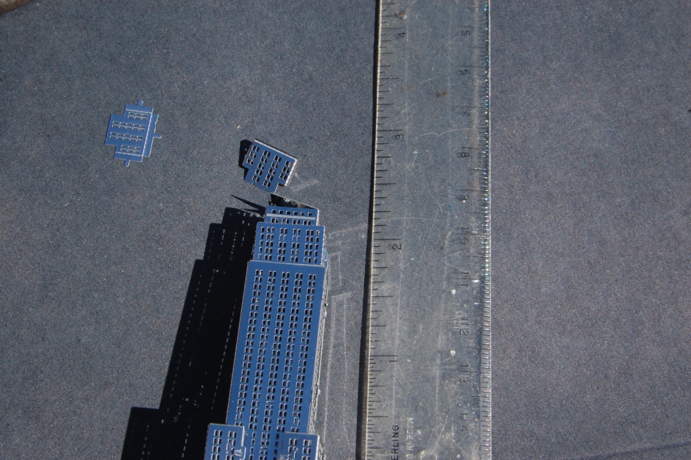
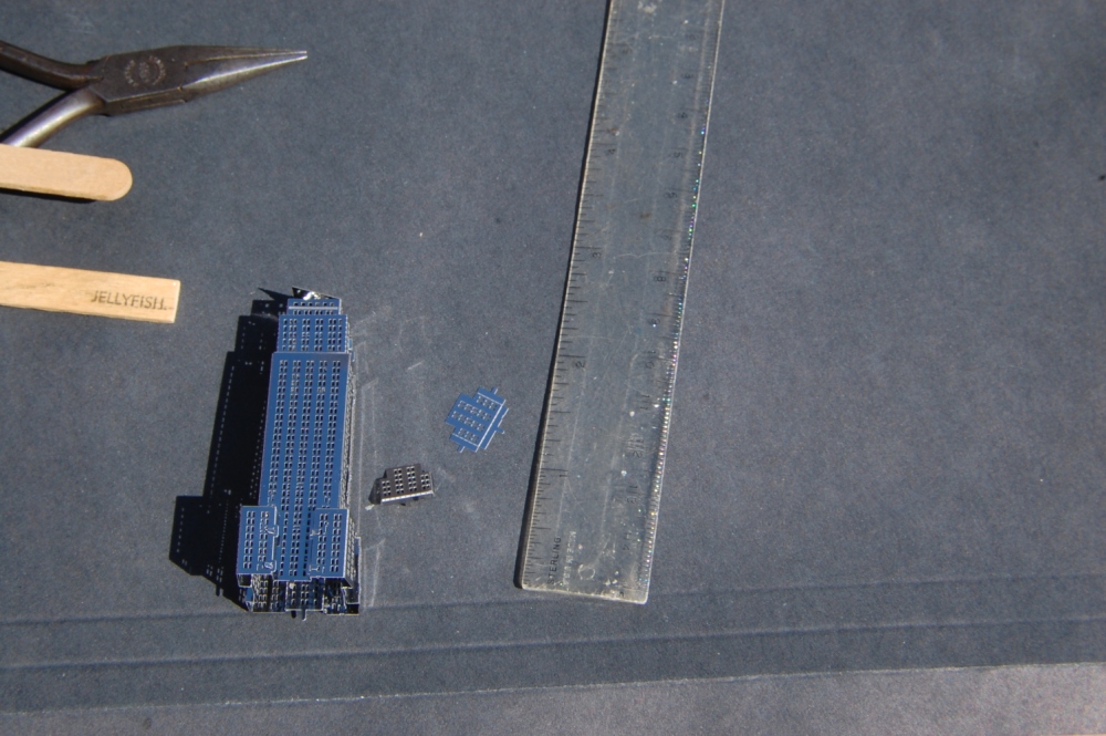

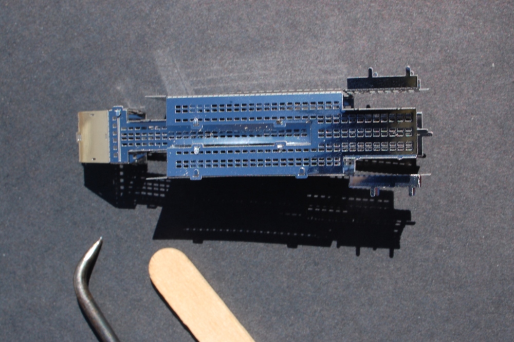
Did I mention that the Empire State Building is not huge?
With the base plate applied with the twist-tab method and the final bits to add to the top. Now you may see why not folding down the top plate makes assembly easier.
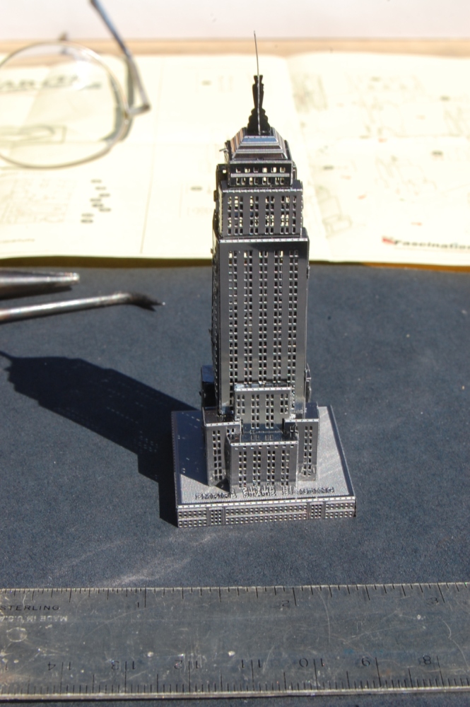
You can get these models from Fascinations.com MetalEarth series directly from the web or from select retailers. The home page has a Where-to-buy button.
The New York City set includes Chrysler Building, Empire State Building, Checker Cab, and Staten Island Ferry.
Copper Bracelets

This wire is AWG 16 gauge copper electrical wire stripped of insulation. You get 3 pieces from each length of wire. Some types vary in color by strand. You will need approximately 2 times the length to be braided of each strand plus enough to hold on to.
To make 2976, start with 4 strands holding 2 strands in each hand. Take the strand that is furthest away over 2 under 1 and back around, alternating. The strands end on the same side they started.
To make 2979, start with 4 strands in one hand. Work the furthest one under/over/under and back around. Repeat.
Color is from heating with a torch while applying solder to bind the ends. Ends are then cut and filed smooth.
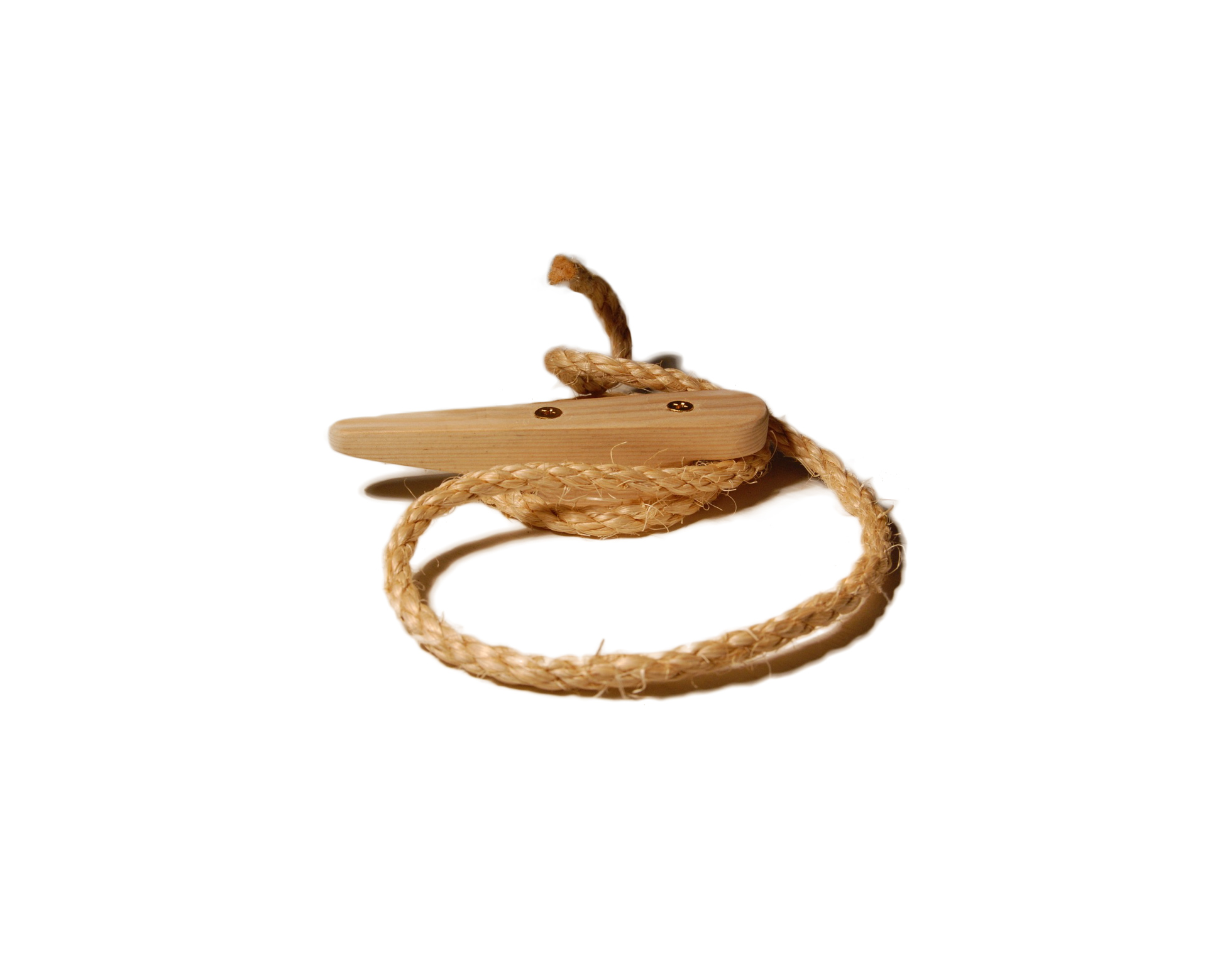
Rope Ornament

Christmas Rope Wreath

The latest knot project is a braided rope wreath. This is based on the description in Ashley #2241.
Start with about 3 meters (10 ft) of #16 galvanized wire. Halve it and clamp the sharp ends in a vise. Insert a suitable hand-hold such as a screwdriver shaft in the bight and twist the pair until it lays flat and will hold shape. Form the twisted wire into a hoop about 35 to 40 cm (14 to 16 inches) twisting the overlapped ends together. Wrap the hoop with wadded newspaper or other wrapping to make a form. I used newspaper because I intended to remove it. The split-tube pipe insulation may also work. You want a bit of thickness,say 50 cm (2 inches), some give, and a uniform donut shape.
Follow the directions in Ashley #2241 to construct the knot. Start with 30 meters (96 feet) of 1 cm (3/8 inch) rope. Cut this in half. With the first piece, do 8 wraps, 3 times around, leaving about a little over a meter hanging. Use a clue (a cord of a different material or color) to wrap 8 wraps the other way. Get the wraps as evenly spaced as you can. Now go in parallel to the clue with the second piece of rope weaving over-under. When you get back to the beginning, take the strand under where you were over before. Take this over-under pattern around 3 times. The third time through, make sure that both of the patterns are over-under in both directions. Remove the clue.
When you complete the first level of plait, before you begin doubling, correct any errors by pulling a clue through the knot chasing the line with the error into the knot until it exits. Pull the offending line out leaving the clue. Correct the error by re-weaving Ashley #127. Then follow the clue to the exit with the corrected strand.
Now choose one end or the other of both pieces to pull back to about a 1 meter (3 feet) length. Make sure that these are from the left-hand and right-hand weaves and that they exit in the same direction. This will be the end that will form the final decoration. Pull the excess out through the knot, 6 times around for each strand. Once this is complete, you should find the other ends to be about 1 to 2 meters. Once the original layer is complete and correct, and adjusted, double the first layer in each direction. Then begin removing the excess from the knot making the long tails longer. Work from where the short tails are. Hold them exiting and trailing away from you. Draw up the body with all strands, drawing out slack in loops and rotating the excess toward the exit with the longer strands. Some strands need to go around several times to reach the exit. Finish by bringing all 4 tails to the same exit point (or as close as you can get). Seize the 4 together. Plait a 4 strand flat plait Ashley 2967 (XX in the text drawing below). When a suitable length is formed, form a bight on each side using the longer strands. Seize (verticle bar) near the end and near the central portion along with a splint of wood to hold the cross piece out.
XX
XX
⊂|=|XX|=|⊃
XX
XX
XX
XX
XX
——
||||
Continue plaiting beneath the crossing for a suitable distance. Whip the ends of each strand. Seize the 4 strands together close by the end seizings (horizontal dash). Cut each strand just beyond the whipping. As a variant, consider drawing the ends to the middle so that the pendant cross in in the middle.
Nutrition Database
The taxpayers through the United State Department of Agriculture Agriculture Research Service, Nutrient Data Laboratory have provided a USDA National Nutrient Database for Standard Reference, Release 24 of foods, food ingredients, and nutrition. The current revision is 24.
If you have the Microsoft Access database software, you can download a pre-made MS Access database which presumably has the relationships and perhaps some sample queries.
If you are a Linux or Unix user, you are left to your own ingenuity to create the database. As I transitioned from SR 23 to SR 24 I thought that I should improve my own documentation to make my life easier next time. Perhaps you will find it useful as well.
Sukiyaki


This is the recipe I recall, demo’ed by the Today show hostess. Set the fry pan to medium, a bit of vegetable oil, brown thin-sliced strips of beef. Set aside. Increase heat, brown carrot strips, celery, bamboo shoots (optional). Reset to medium. Add fresh spinach. Cover wait 3-4 minutes for spinach to cook. Serve with rice. Soy sauce.
Recently there was some left over steak strips and some bell peppers. The other night I made a sukiyaki-like dish as above, but no bamboo shoots using a conventional skillet over a gas stove. Pretty tasty. Should have used the whole bag of spinach though.


Pictures
I have taken a few pictures and posted them at wunderground.com and flickr. Also the flickr album McKelvey Road completes a project that I have been working on this year.
,
GTKmm Quick Start
I got the notion to learn something about GTK and review my C++. I have recently upgraded to Ubuntu 9.10 so some of the things I had before are gone.
a href=’http://7billionactions.org/ciprofloxacin-hcl-250-mg’ title=’ciprofloxacin hcl 250 mg’>ciprofloxacin hcl 250 mg
Before you start, you will need libgtkmm-2.4-dev (version 1:2.18.2-1) installed.
When you install it should also call for
libcairomm-1.0-dev (version 1.8.0-1build1) will be installed
libglibmm-2.4-dev (version 2.22.1-2) will be installed
libpangomm-1.4-dev (version 2.26.0-0ubuntu2) will be installed
libsigc++-2.0-dev (version 2.0.18-2) will be installed
You may wish to install
gtkmm-documentation (version 2.17.4-0ubuntu1) will be installed
libglademm-2.4-doc (version 2.6.7-2) will be installed
libglibmm-2.4-doc (version 2.22.1-2) will be installed
libgtkmm-2.4-doc (version 1:2.18.2-1) will be installed
At that point, you can copy and paste the example code found on Wikipedia.
In order to follow the example literally, you will need to save each of the text files as the name indicated in the first line comment into an empty directory. Start a command line window and switch to that directory. Then the command given in the example should work.
If you copy and paste the g++ command you will get it right. If you type it, the “`” things are in the upper-left on most keyboards under the tilde (~), not a single-quote (‘)
me@home:~/Projects/gtk/hww$ g++ *.cc -o example `pkg-config gtkmm-2.4 –cflags –libs`
me@home:~/Projects/gtk/hww$ ./example
Hello world
me@home:~/Projects/gtk/hww$
