My son’s girlfriend gave me a great Christmas gift.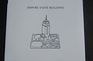
In one shot it satisfies my longing for metal-working, model making, real estate, architecture. WOW!
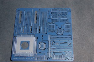
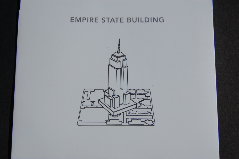
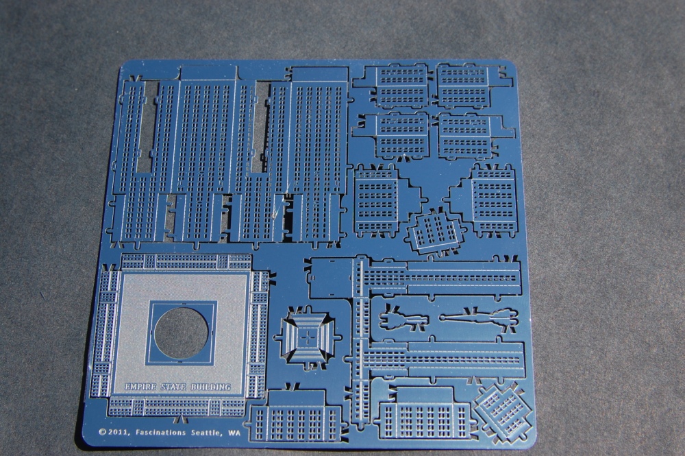
These laser-cut pieces of sheet metal can be re-arranged into actual models of things New York City, New York
I previously put together the model of the Chrysler Building but have not yet posted the pictures. In this post, I will discuss the Empire State Building

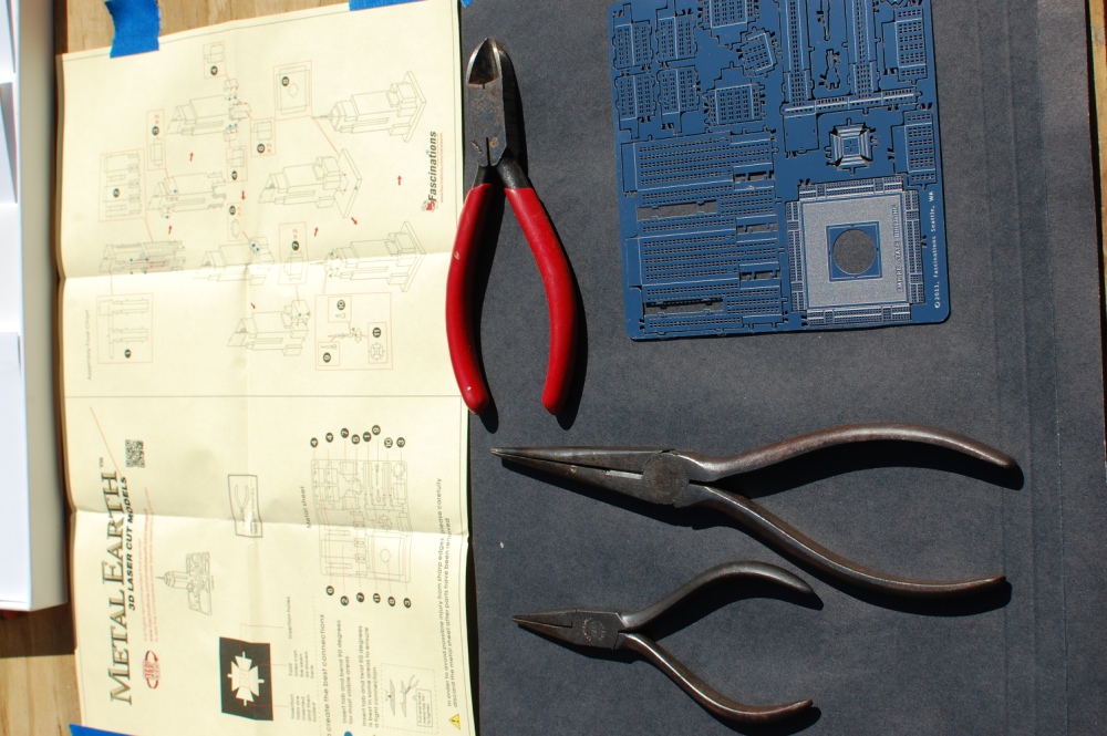
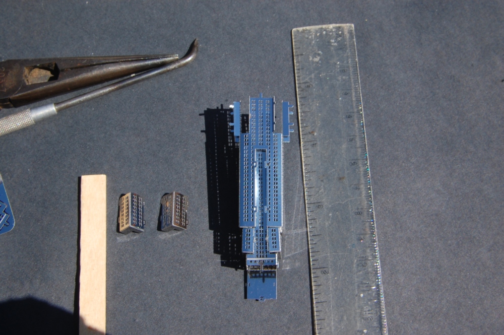
I have shown some of the tools that I used to assemble the Chrysler building but as always, experience teaches and I added a couple tools, tips, and techniques down the road. I tried to rotate the image so that the instructions were on top but it did not seem to take. If you buy the kits, you will get a separate instruction sheet for each model.
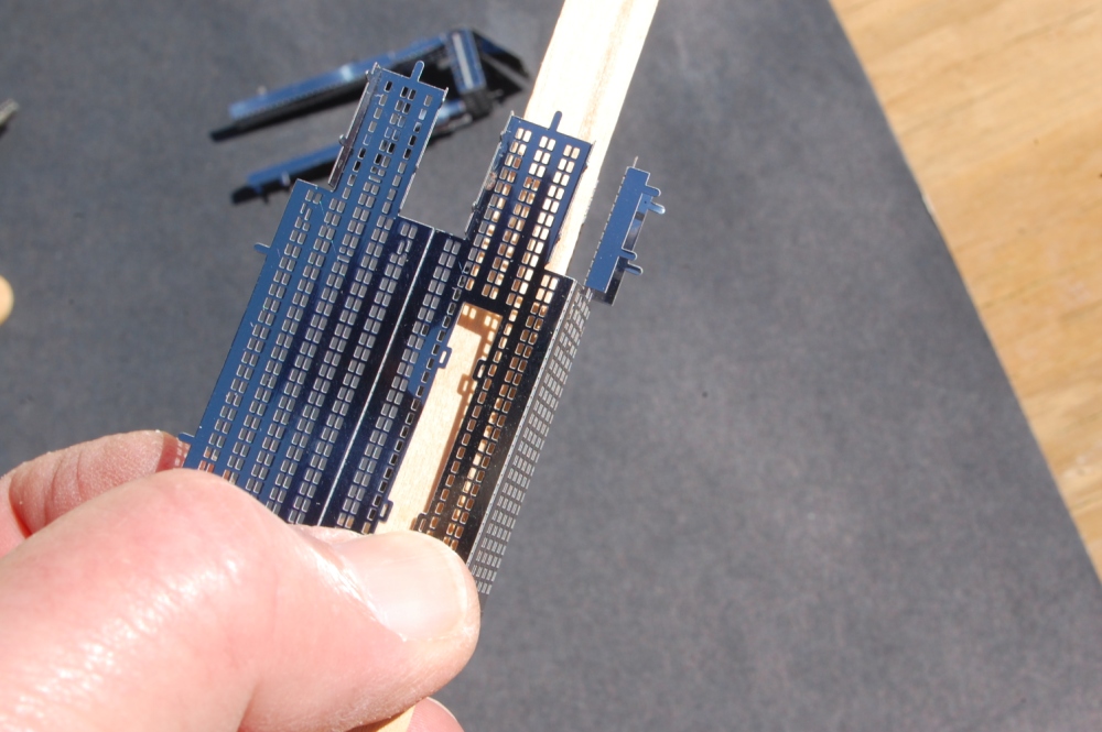
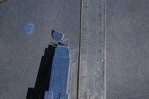
The diagonal cutters may be useful on the larger pieces that are anchored in three places to break the third point so the model piece can be rotated about the other pair of points to get it to separate. Be careful not accidentally flex or bend the individual pieces while removing them from the carrier flat sheet.
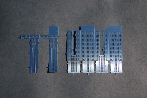
The pieces have folds. The dotted-line folds are “valley folds”. The solid line folds are “mountain folds”. Only make the folds as described by the directions. Making a fold too early may make a later assembly difficult.

Visible joints are tab-thru-slot folded over. The hidden ones, mostly on the base, are tab-thru-slot twisted to tighten. The instruction sheet notes these with an icon dipicting the correct technique.
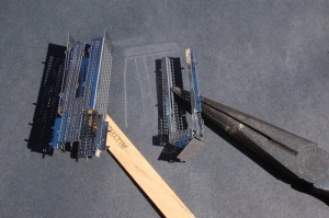
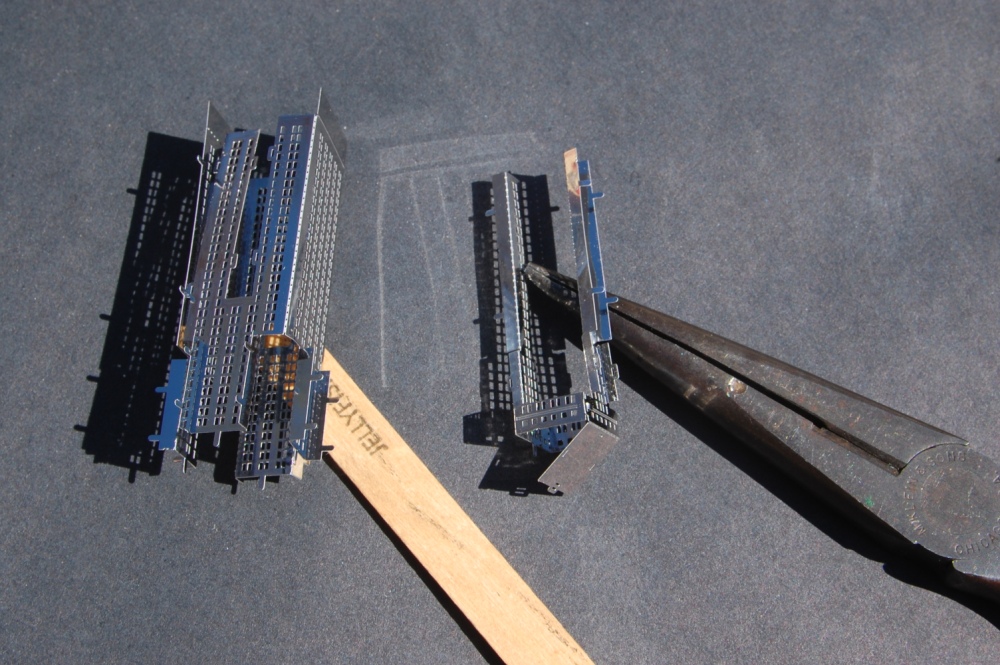
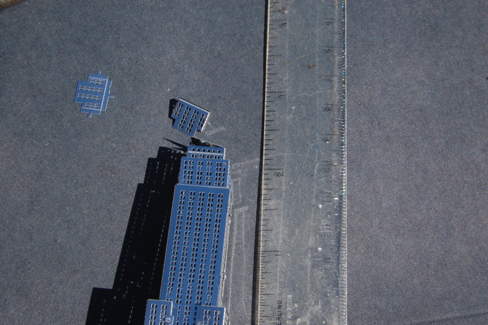
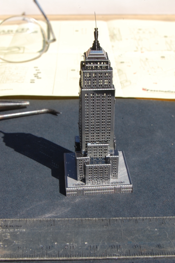
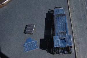
The architectural and visual interest of the Empire State Building comes from its intersecting solid volumes. To construct these from sheet metal makes the challenge of marrying two not-quite square folded sheets and getting all of the tabs to line up with all of the slots. I found that the Popsicle stick, a scribe, the needle-nose pliers and a lot of patience were all helpful.
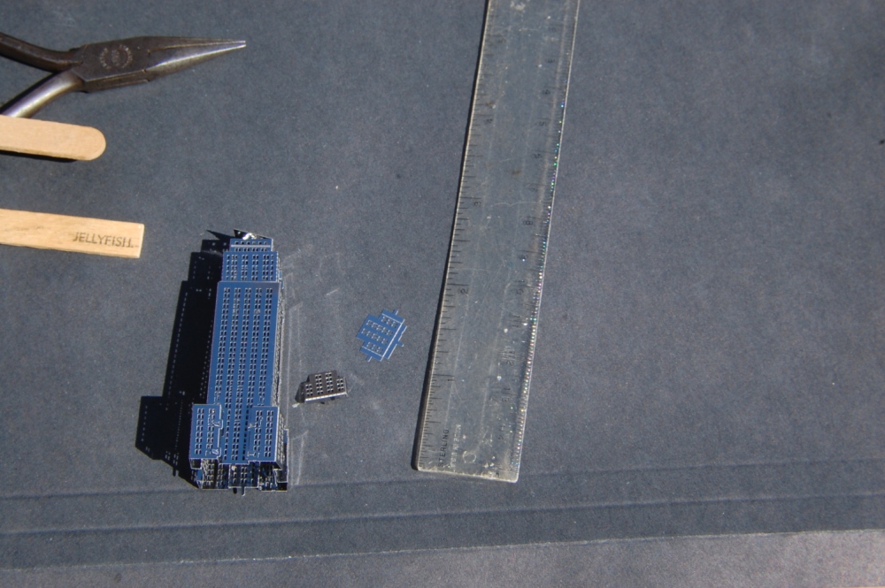
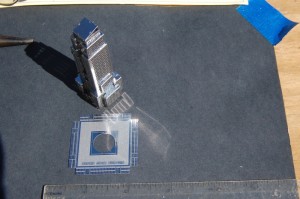
I realized as I was working that some of the longer folds were difficult to keep flat and square without a hard surface with a flat edge. I made a “brake” from a Popsicle stick that helped make the folds flat and square without distorting the adjacent surface. Cut one of the rounded ends off square with a hobby-knife or fine saw. You can also use this tool as a poker to flatten internal tabs or to flatten a surface that has been pushed in too far during assembly.

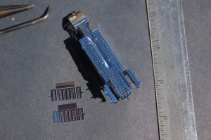
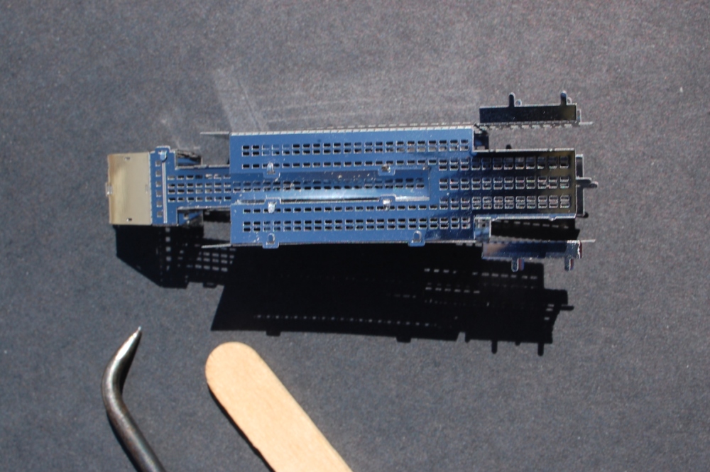
You may be able to see that I squeezed to hard and curved a side that needs to be flat. Using the edge of Popsicle stick was helpful in correcting this problem. In each of the following illustrations, I have tried to be faithful to the directions by showing the pieces to be added and in the next picture how they look after they are installed.
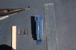

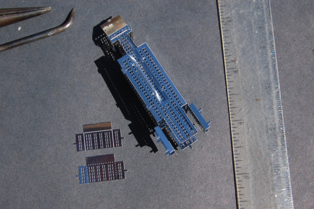
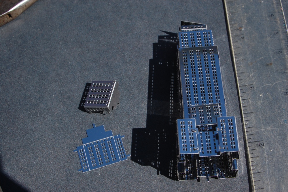
Did I mention that the Empire State Building is not huge?
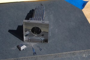
With the base plate applied with the twist-tab method and the final bits to add to the top. Now you may see why not folding down the top plate makes assembly easier.

You can get these models from Fascinations.com MetalEarth series directly from the web or from select retailers. The home page has a Where-to-buy button.
The New York City set includes Chrysler Building, Empire State Building, Checker Cab, and Staten Island Ferry.