License Plate Light

A neighbor stopped me to tell me that my license plate light was out.  I thanked him and said that I would take care of it.  That was almost two weeks ago.  Last weekend, I did get the correct bulb at the parts store but did not get it changed. Here is what I did yesterday.

The socket itself is retained by two small TORX screws.  I have two drivers but it was smaller than either.  I got a bit from the “security bit set” that I had recently purchased at Harbor Freight.  This kit contains an assortment of sizes of every odd bit for odd screws. The kit has a 1/4-in drive bit holder.  I used a 3/8-in drive extension and a 3/8-1/4-in adapter to make a screwdriver to remove the screws. The lamp housing was stuck to the license plate recess so I used a putty knife to gently separate it.  The lamp was cracked but came out easily.  It was clearly burned out.  The housing was also cracked, problably from frozen water.  I sealed it with Goop brand sealant/glue. When I inserted the new bulb, it did not make contact initially.  There was some grease or silicone gunk that kept it from making good contact.  Wiggling the bulb got it to work.  Re-assembly reverse of disassembly.  Phillip and I also checked all of the lights on all three cars and topped up the mini-spares.

Icemaker Repair II – part 2

The previous post talks about the problem with the ice maker. This is about the fix.
Basic ice maker theory. 1. Put water in a container. 2. Put it in a cold place and 3. wait until it freezes. 4. Warm the container until the ice is loose enough to come out. Repeat.
Automatic ice maker theory. Actually begins with step 3 since this is where you will find the automatic ice maker most of the time. There is a thermal switch that detects when the container (and the ice inside) is at a frozen temperature. When this happens, the switch closes and the motor rotates the paddles. A switch turns a heater to warm the ice mold to loosen the ice. The paddles push against the ice.. The motor will push the paddles against the ice until the ice releases. When the ice releases, the paddles continue around and push the ice into the catcher. At some point the heater turns off and the water is turned on to refill the mold. There is a small slotted adjuster on the side of the unit that sets the amount of water and hence the size of the ice chunks.
My unit was somehow jammed. I poured about 1/8 cup (.03 liter) of water to get the cubes loose. The paddles rotated and the cubes came out. It refilled normally. The water going in made a noise like the mold might have been really hot. The ice made in about 20 minutes and came out normally. I reduced the cube size slightly (clockwise 1/16 turn of the slot with my thumbnail) to reduce the force required to push out the cubes.
It is still working a week later.

Chairs

Our dining room set was moderately expensive 25 years ago. It has held up well. But it is “factory made”, not “craftsman made”. The worst part of the factory is the machines that shoot staples and some sort of flat metal thing into the joints. These make repairs impossible. These items probably stabilize the joints while the glue dries. Because they are impossible to extract and damage the wood when they go in, they weaken the joint to begin with and make repairs impossible later when the joint lets go. I would recommend that Congress ban the domestic manufacture of furniture using these devices and the import of same.

Chair Repair

Today’s project was the re-assembly of a chair that was disassembled 3 weeks ago. The nature of chair assembly is that once you begin, you must finish all of the stick together parts in one session. The screw together parts can be done later but because of the way chairs are, they need to go together all at once. Allow adequate time. The three week lag was because I did not have a clear spot on a weekend long enough to keep it open ended.Let inertia work for you.

The first step in chair repair is get the chair completely apart. If the chair has failed catastrophically, there may be broken parts along with parts that are still quite tight together. If the chair is just wiggly and loose, many of the joints are probably ready to come apart with the appropriate amount of force. It may be difficult but you must make sure that you have all of the pieces that will or can come loose, loose.

IMPORTANT – as you remove each piece, mark it so that it can be re-assembled in the correct orientation. Make the left of the chair as you sit in it the left. Mark each piece in an inconspicuous spot with Front/Left/Top etc. so that you cannot be confused when it is time to assemble.

CAUTION – watch for modern short cuts that may render your chair difficult or impossible to repair. Staples, pins, repair plates, steel wedges are difficult to remove, damage the wood fibers and are the topic of another future blog entry.

Disassembly proceeds easily at first and then becomes more difficult as the pieces get harder to separate. For large pieces, this can mean working them apart by pulling and wiggling. I find wiggling the piece in a rotating pattern with occasional reversal of direct the most effective. Sometimes rocking side to side is best. Rarely, you may need to wedge some like a stick of wood where the scars will not show and leverage against it to get movement.

Another technique is the tap. Tapping with a rubber mallet can do the trick. Mine is white rubber and does not mark. A hammer, carpenter’s hammer or machinist’s, provide a firmer force. Protect the struck piece with a smooth piece of scrap. The sharp blow of a hard hammer may be more effective at breaking a glue joint. Let inertia work for you. Watch the rebound.

Once you have all of the big pieces apart, try and get the pegs out. Grasp the peg with a pair of slip-joint pliers. See if there is any movement at all. If there is, try to work the peg out its hole. If there is no play and tapping does not loosen it, skip it.

Inspect the pegs. Replace any that are cracked and those that have left a chunk in the hole.

Check the holes. Clean them out with a drill of the appropriate size. Remove any glue left in the hole. Modern glues may not stick to themselves or other glues. Old glue, such as hide glue needs to be renewed so get it out of there.

Clean up the ends of the rungs and the holes in the spindles and rails. Use 60 grit or 40 grit sandpaper to get the glue of and the pegs and pieces smooth. Get everything cleaned up for smooth re-assembly.

Once you have it apart, lay out the parts in the order that you are going to assemble them. Some chairs have to be assembled all 4 corners at once. Others like the one I was working on today can be assembled from front to back or back to front.

The first assembly is a dry assembly. It helps you to do the final assembly correctly and easily.

For my chair, I joined the two front legs with a rung, 4 pegs, and the front piece. Observe the surfaces and the left to right orientation. This I laid flat on the floor. I then added 2 rungs and a side piece on each side.

Separately, I assembled the back. There were 4 back slats, the back seat support, and a rung (which I could not get out). I then put the back onto the front. I noticed as I was doing this a hole that retained a piece of the peg. An I had replaced the peg with a fresh one because it was split. If I had been working with glue, I would not have had time to clean up the hole and get it together before the rest of the chair got too stiff to work with. This is why we do a dry assembly.

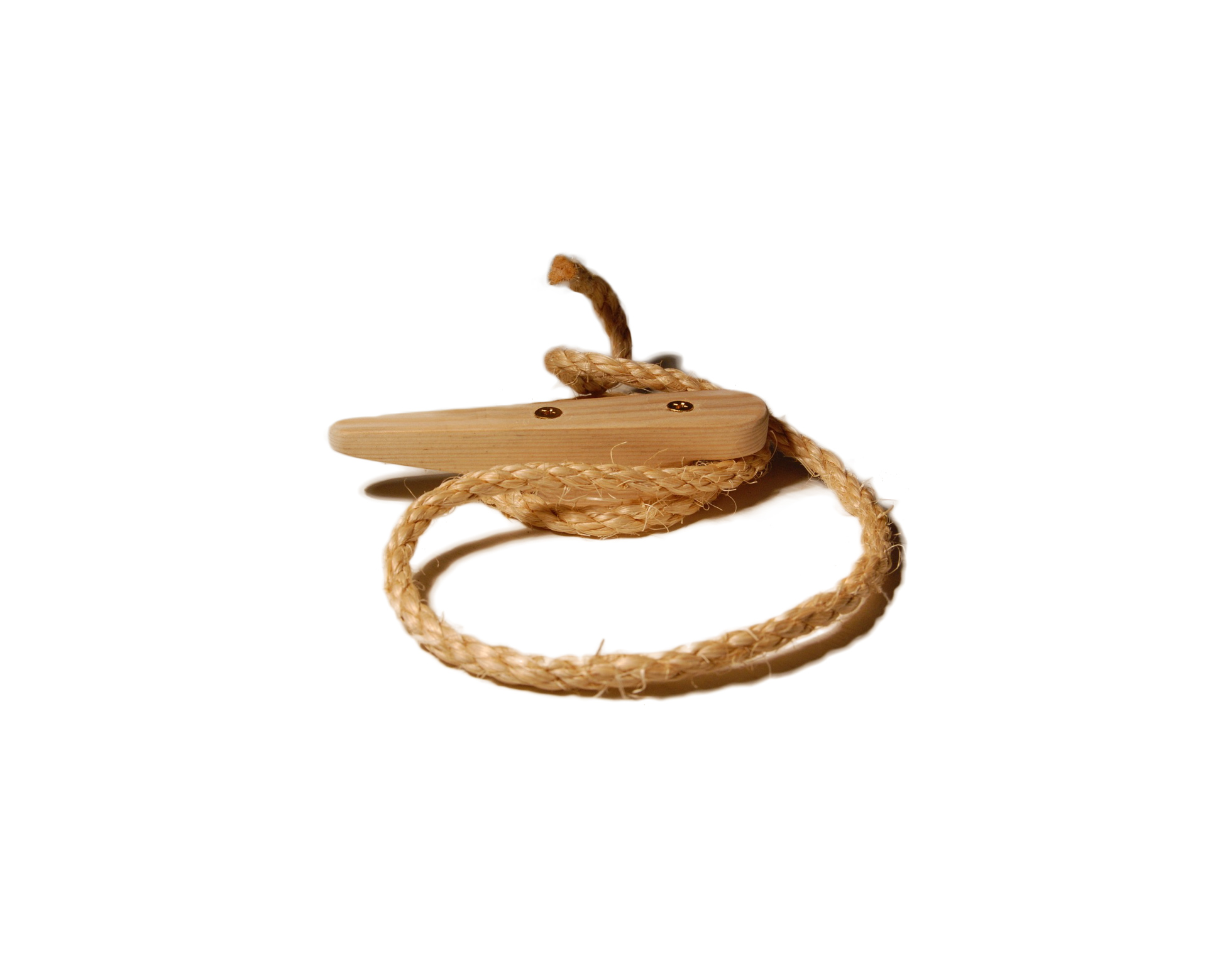
Work out how you will put the clamps on to pull everything up tight. You may want bar clamps ( quick-clamps work well) or a rope clamp. I used both.

Take it all apart again and lay it out neatly.

For the final assembly, I used Chair-Loc . I have used this in the past and it is good for about 7 years of daily use on these chairs. The chair I worked on today did not get completely disassembled last time I did repairs and so it has never really been tightened up in 25 years.

Repeat the assembly this time putting Chair-loc in each hole and spreading it around each peg or rung. Press everything together. Clamp it, tap it and get it real snug.

Give it a while to set up, put the seat on and screw in the screws.

The chair is now nice and tight.
Cat Bed

I have made a number of beds for the cats. This is a fairly quick and simple project. You need a table saw or a router with a 1/4 inch cutter that will cut to 3/8 inch depth.

I noticed that the cats liked cardboard and corrugated boxes and box lids of a certain size. This is the size that I made the box out of wood. The sides are a little higher than the preferred lids but my wife makes Polar Fleece “puffs” to fill the bottom and the cats seem to like them.

The first box lid that the cats liked was the tray that came in the citrus fruit from Florida. This tray had doubled sides and seemed to be a particular favorite of the cats and so became the model for size and proportion. This one is 16 by 10 1/2 inside. This makes the length 17 1/2 and the width 12 inches.

The basic idea is simple. Four sides and a bottom. The bottom is fairly fixed. It is 1/4 inch plywood. The sides give lots of options.

The first option is the choice of material. Pine, oak, and cedar are good choices. Pine is inexpensive and easy to find and work with. Oak is pricey and pretty. Oak looks good indoors and ages gracefully outdoors. Cedar is rot resistant and can be pretty. Not too expensive but cedar splits easily if the corner screws are over tightened. The height can by the 5 1/2 inch width of 1 by 6 or the 7 1/2 inch width of 1 by 8. And a couple that we have are from 1 by 4. Of course the 1 by is 3/4 inch thick.

The box construction is straight-forward. A rectangle with the long sides (length) overlapping the ends (width). The bottom is set in a groove around the bottom. The groove is 3/8 inch deep in the 3/4 inch thick sides. Cut the plywood about 5/8 inch wider than the width and 7/8 inch shorter than the length.

For the box above, this would be 2 pieces 17 1/2 inches and 2 pieces 10 1/2 inches. The bottom is 16 5/8 by 11 1/8.

NOTE: Follow all general and specific safety instructions for the tools you use.

Cut the side and ends to length. Set the saw blade (or router cutter) height to 3/8 inch above the table and remove the splitter so that you can dado a grove. Be very careful if this leaves the blade unguarded. Check the height with a piece of scrap and adjust it until it is just the right height. If you are using a router, you and your router may be happier and your cutter may last longer if you make several passes increasing the depth until the final depth is reached.

Set the fence so the close edge of the blade is 3/8 from the fence. Carefully make a pass through each piece. If you are using a 1/8 inch saw blade go on to the next step. If you are using a 1/4 inch router cutter, skip the next step.

Reset the fence so that the far edge of the blade is 5/8 from the fence and just a scosch more. Test it with the scrap. Try the plywood bottom for fit in the slot. If it is loose, move the fence closer. If tight, move the fence a bit farther way. When adjusted, make sure that you hold the previously cut edge toward the fence and carefully make a pass through each piece. When you have cut both sides, you may need to clean out the bottom of the groove with a 1/4 inch chisel.
You now have a 1/4 inch groove in all 4 pieces.

Trial fit the sides and ends against the plywood. The plywood should fully close the bottom. The sides should mate up tightly against ends.

Drill and countersink a hole in each side 1 1/4 inch from the bottom and another 1 inch from the top. IMPORTANT: Assemble with brass screws. Steel screws and galvanized screws will leave stains on the wood. Brass screws will turn a pretty verdigris if they do anything.

Line with a blanket made from Polar Fleece. Make sure that there are several thicknesses and that the ends and sides of the liner extend beyond the wooden sides.

Reviving the Hammond

I have a Hammond organ. I have had it since my dad moved it from his garage to my house in Connecticut. Before that it had been in my grandparents house. I used to play it occasionally in Connecticut as did my wife. But since we have lived here, it has been played maybe once. My wife re-arranged the room that it is in about 8 years ago and the speaker cable got disconnected and it has not been powered on in all that time.

Tonight, my son, 17, decided that it needed to be played. We had tried it a couple of weeks ago and knew that it was stuck. The oil had dried out and it was not turning when the start switch was on. Tonight when his friend was here, they picked it up and moved it out a bit from the wall. I took the back off and loosened up the rotor shaft. The start switch would get it to turn but it would not run. I got some light oil and put it in the oil cups. It dripped down the tubes and into the wicks. Still no go. We went and did something else for about half-an-hour. Now it ran but the bearing was still a bit noisy. After a minute of playing, it settled down and was quiet. Phillip played it for about an hour trying various combinations of drawbar settings. Quite exciting. This little bit of machinery and electronics was made sometime between 1935 and 1940. The predecessor of the Hammond B-3. We need to make sure that we play it often and that we oil it with the proper Hammond Oil next time.

Car Lights

A neighbor followed my wife into the neighborhood a few nights ago. Actually he was driving a car following her car as she drove into the neighborhood. He saw that some of her lights were out and should be replaced.

My son pointed out that unless you have someone walk around your car regularly while you signal and tap the brake, you never really know what lights are working.

So Phillip and I did a light check on each of the cars and made a list. I took the list to — and got $28 worth of bulbs. Then I spent the afternoon replacing bulbs.

First the Buick – The Buick has a lighted trim strip in the back. What appeared to be 1 light out on the left was actually 3 – 2 bulbs on the left and one on the right. The bulbs are inside an assembly that is held on with 6 wing nuts. These nuts are a neat design that you can use a socket wrench on with an electric screw driver but you can get them off by hand. This job would have been straight forward except for the broken bulb that crunched when I tried to turn it. Careful work with a soft-jaw plier did the trick. The other bulb was one of two high brake lights. These are easy to reach from inside the trunk.

Then the Cavalier – Two high brake lights out. Again easy to reach. The right turn signal light requires removal of the entire headlight assembly. Remove the bulb holder, change the bulb, and put it all back.

Then my Olds Cutlass Cruiser – The problem here is that the dashboard light was out on the left side. This kept the engine temp gauge in the dark. I am a bit paranoid about the engine temp since a bit of overheat cost be about $1200 a couple of years ago. Getting at the bulbs requires removing all of the dashboard trim (6 screws), the instrument cluster (4 screws) only to find that the bulbs that the store computer called out were just the bulb. For the dashboard, you need a special assembly of the bulb and its mounting plate. I re-arranged the bulbs so now the dark part of the dashboard is from 60-120 MPH. Not a part of the speedometer that I use a lot.

Lights and Luck

Yesterday I picked up the Wall Street Journal and looked at the weather map. I saw that there was a cold front with thunderstorms along it due. I put on my hat to leave for work and noted that there was rain just beginning. As my son and I got into the car, the rain began. Ten minutes later as we were moving along the freeway, the rain was very hard and steady. The sky was dark enough that the dashboard lights were quite visible. I noted at this point that moving the bulbs around on the back of the dashboard module had moved the dead bulb to the over-65 side of the speedometer and the formerly dark side now had light. Sometimes you get lucky.

Smoke

My son reminded me that we should replace the smoke detectors that came with the house. We have been here 13 years and the USFA suggests that 10 years is the life of a smoke detector.

User requirements: Same size as old model – no repainting or touch up. AC power. Common Alarm.

I found a replacement at Lowe’s in a 2-pack. Just what we need. When I told Phillip that he would be doing the installation, he was a bit taken aback. He has never done the electrical work. He found the circuit breaker while I was at work since he had a holiday off. We needed to replace the connector plug for each unit as the new detectors were a different brand than the ones the builder had installed.

He did the first unit but somehow the wire nuts did not connect properly. May they just needed a bit more twist as that is all that I did. On the second unit, he was uncertain that the circuit was dead and was reluctant to work on it. He did point out that the thing had not had power for some time as the hot lead had pulled out of the old plug and was loose in the box. It was a plastic box or it would have shorted and blown the breaker. Even though I pointed out that it was the “middle” of the circuit as a pair of black and white came into the box and another left and we could tell that the other unit was off, he let me do this one.

After much discussion about the radioactive ion detector, Phillip found a source on the web that said that we could dispose of the units in the trash. So I threw them in the covered trash can in the kitchen. A couple of days later, before the trash went out, they started to chirp. I had not checked that the batteries were removed and the decomposition products in the trash were enough to set them off. I had to fish them out and get the batteries out.

We also discovered that the Elvis, our cat that is blind and mostly deaf, can hear the smoke alarm just fine. He starts singing at the top of his lungs when he hears it. If there is a problem, we will not be forgetting him.

Cat Flap

I finally got the cat flap into the garage fixed. About a year ago, there was some kind of commotion that resulted in the door on the cat flap breaking. I was able to repair it but a repeat this Spring resulted in permanent damage. So the cat flap has been open all summer. With Fall, there are other animals coming in and it needed to get fixed.

The part that broken was the clear plastic door. Our cats like a rigid door that they can see through. Some of them charge right through but others tap the door with paw or forehead and take a peek before diving in. Also Mr. Hillard is a substantial 19 pounds (8.6 kg), (but not fat!). I previously, I got a larger flexible flap for the window and they did not care for it.

The flap is in the aluminum garage door which is effectively zero thickness. When I did the original installation, it was straightforward sheet metal work that the US Navy trained me for at taxpayer expense.

To get it fixed, I had had some e-mail correspondence with the manufacturer of the old door, Stay-Well. They offered replacement parts for the model 715 but could not tell me where I could buy a complete replacement locally. While I was on vacation, I went to Tractor Supply (they have a lot of pet supplies) and Pet Smart but both were out of the small inexpensive door and and only had the deluxe models with locks and magnetic keys. Our cats do not wear collars and “lose” them if they get them for flea treatment and such. So no kind of key system is appropriate. Just a simple door please. Tractor Supply was out on both visits. Pet Smart was out on the first two visits but the helpful person in the aisle said come back Tuesday. Well I did not make it back Tuesday but I did make it back 2 weeks later on Friday when I had to go up to Pep Boys on Laurens Road. So I stopped by and there was almost what I needed. The Stay Well I had before and the Petsafe door I could buy now are different sizes.

There are some other differences. The Petsafe door has a label which describes the flap as being clear. But the label is over the flap and you do not really see that it is dark gray. It has mounting for a wooden door but not a sheet metal door. And the trim which goes on the other side from the mounting is to be applied with double-stick foam. It does not have relief or sockets for the sheet-metal screws the are supplied.

Fortunately, the new door was wider than the old door. More of those taxpayer funded skills with a tip of the hat to Mr. Hooper, my eighth grade metal shop teacher.

Raise the door and rest it on a saw horse. Using the template provided with the new door, I marked the new cut line with a permanent marking pen. Clamp a block behind the door with a spring clamp and center punch the corner hole locations 1/16″ in from the corner so that the cut lines are tangent to the hole. Repeat for the other corner (corners if this is a new install). Drill the holes with a 1/8″ drill. Cut with a metal shear along the line. Draw file the edge of the hole and burnish with a drill rod or scribe to remove the burrs. Hold the door over the hole and get it aligned. Mark the screw hold locations with a pencil. Again clamp the backing block, center punch the holes, drill them with a 1/8″ drill. I used 1/2″ long 8-32 screw, nuts along with a washer to mount the door. I put the hardware in from the outside because I did not expect the trim frame piece to stick to the textured and simulated raised panel door. It is stuck on the inside. With the hardware in the weather, it will eventually corrode. I finished this up about 14:00.

The garage door was up most of the afternoon while we were working outside. I put it down at about 17:00. About 17:30, Mr. Hillard came through so things are fine.