The mouse wheel on the mouse that came with the Dell 8100 stopped working. Or at least is worked intermittently. If you moved your finger v-e-r-y slowly, you could get scroll to move. But the detent was too stiff for rapid moves. And of course applying more pressure clicked the middle button. I decided that there was slippage and determined to find out why.

The tire has been rolled off of the hub in Figure 1. What I found was that there was an oily substance between the hub and the tire. I used a piece of tissue, water with a touch of detergent (actually still in the sink from the lunch dishes) to clean the hub and the inside of the tire.

Plug the mouse into a computer and test its function.
While I did not disassemble another mouse, a Dynex, I noted that the screw is not visible. If you do not see a screw, probe or remove any label on the bottom to locate a screw. Another possibility is a snap-together arrangement. I suspect the insides will be similar to the pictures of the Dell mouse.
Lawnmower Starter Rope Replacement

The other week when I pulled the rope on the mower, the rope broke off. Fortunately, the mower started and I just had the rest of the back yard to do. I finished it up, waited for the mower to cool and started the repair job.

My mower is a Yard Machines by MTD 22-inch side-discharge high-wheeler that I bought 15 years ago.
I have replaced the rope at least a couple of times. Here is how I do it.
For safety, disconnect the sparkplug wire from the sparkplug by pulling on the rubber cover.
There are two screws that retain the top cover. The screwdriver is pointing to one of them, the other is on located on the nearer side. Remove the screws with a Phillips screwdriver. Remove the top cover noting the index tab at the rear that engages the fuel tank. Also note the slot where cover allows the pull rope to pass through.

Using a 5/16″ socket, break the 3 hex bolts on the top of fuel tank ring loose (Figure 2). Using a 5/8″ socket, remove the bolt located under the fuel tank (Figure 3). Catch the spacer that is located between the engine block and the tab on the fuel tank. Remove the 3 screws on top. Lift and tilt the fuel tank toward the rear of the mower. It will remain attached by the fuel line.

The metal engine shroud is now exposed. Brush any dirt away from the lower end of the oil filler pipe where it enters the engine block. The oil filler will be loosened but not removed. But if it does fall out, cleaning will prevent dirt from falling into the crankcase.

There are two bolts on the front of the engine (Figure 4) and two bolts (Figure 5) on the back of the engine and the bolt that holds the oil filler. Using a 3/8″ socket, break loose the two front bolts and the two rear bolts. Use a 5/16″ socket to remove the bolt on the oil filler neck. Gently lift the oil filler neck to disengage the peg that holds the oil filler neck to the shroud. Twist oil filler neck slightly to get it out of the way.
Using the 3/8″ socket, remove the 2 screws each at the front and rear. Now lift straight up to remove the shroud and pull-start assemble. The starter will come out of the cup that is on top of the flywheel which engages the ratchet of the pull starter.

Looking at the underside of the shroud, you can see the pulley that the starter rope needs to run around. A tube inside the rim of the pulley (at approximately 9 o’clock position Figure 7) is where the starter rope needs to be attached. There is a small peg located opposite that will assist in winding the starter rope take-up spring.
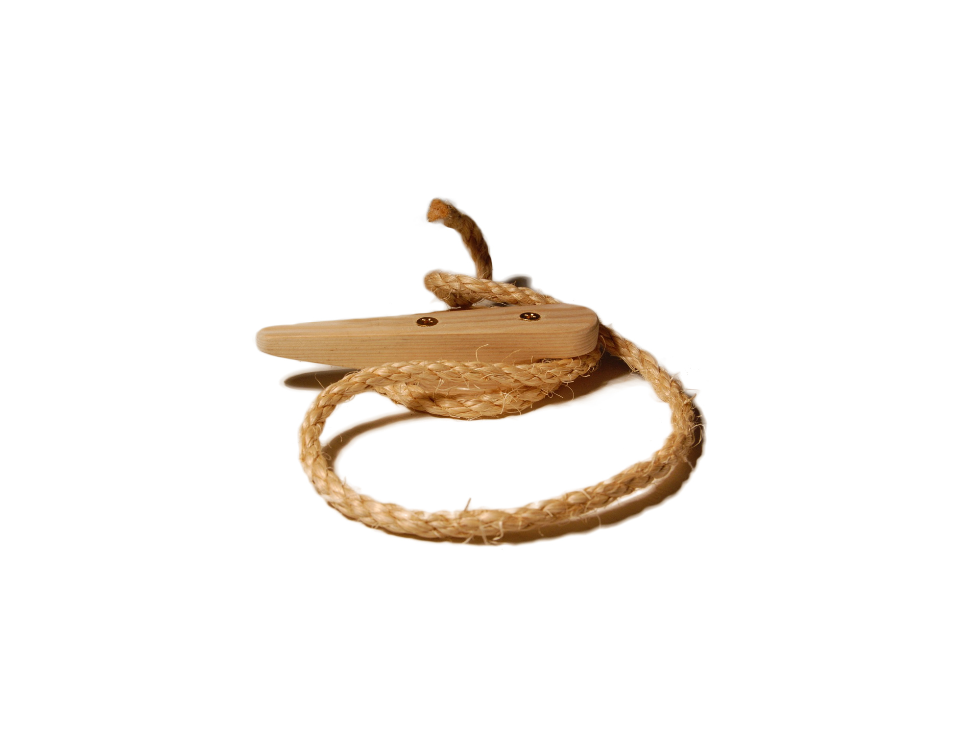
Make sure the starter rope end is ready. Measure the new rope against the old and cut to length. Use a figure-8 knot to hold the rope in the handle. A new rope will have the nylon melted and may be ready to go. The melted portion should be no larger than the rope diameter (Figure 6). If it too large or you have trouble inserting it in the next step, heat the end of the rope with a flame or soldering iron. Use two pieces of wood to roll it into a pointed shape. Be Careful: Hot nylon can give you a nasty burn.


As you wind the pulley in a counter-clockwise direction, not that as you begin to feel tension on the spring, the ratchet levers are pushed out of the center area. These will engage the ridges in the cup that is on top of the flywheel. Continue winding the pulley 3 turns stopping when the tube is lined up with the hole in the shroud where the starter rope comes through. Push the pointed end of rope through the shroud and through the tube (Figure 8). Tie a figure-8 knot in the end. Slowly feed the rope into pulley as it unwinds. When the spring is relaxed, there should be slightly less rope exposed than it takes to reach the location on the mower handle. This slight bit of tension keeps the handle from drooping. If the rope is too long, stretch it out, re-tensioning the spring, draw in a few inches and tie a new knot.
Lower the shroud over the flywheel. Align the bolt holes, insert and finger tighten 1 bolt front and 1 bolt back. Verify the operation of starter ratchet. Release the blade-brake and pull the engine. Verify that the starter rope rewinds. Insert and finger tighten the remaining bolts on the block. Carefully, so that it does not pull out, position the peg of the oil-filler neck back in the hole in the shroud. Insert the bold and tighten. Tighten the 4 bolts front and rear.

Pass the handle and rope through the mounting ring of the fuel tank. Reposition the fuel tank on top of the shroud. Insert and finger tighten the 3 bolts on the ring. Under the fuel tank, insert the long, shouldered bolt through the tab on the fuel tank, then through the spacer (located above the end of the finger in Figure 9) , and finally into the engine block. Verify the adjustment and tighten all bolts.
Loosen the starter-rope guide on the handle to slip the rope into it. There should be a slight tension. Just enough to hold the handle in place. If the rope is too short, it will put tension on the spring and wear the ratchet. If too long, the handle will droop and snag shrubbery as you mow. Verify operation by pulling the engine with the blade brake off and allowing the starter rope to re-wind. If any of these checks are out, redo the steps above to make the appropriate adjustments. Reconnect the spark plug. Mower is ready to use again.
Sukiyaki


This is the recipe I recall, demo’ed by the Today show hostess. Set the fry pan to medium, a bit of vegetable oil, brown thin-sliced strips of beef. Set aside. Increase heat, brown carrot strips, celery, bamboo shoots (optional). Reset to medium. Add fresh spinach. Cover wait 3-4 minutes for spinach to cook. Serve with rice. Soy sauce.
Recently there was some left over steak strips and some bell peppers. The other night I made a sukiyaki-like dish as above, but no bamboo shoots using a conventional skillet over a gas stove. Pretty tasty. Should have used the whole bag of spinach though.


Oven Ignitor Replacement
The Amana oven ignitor failed. Of course you only notice that when you are about to use it. Fortunately it was something that just needed heated, not a cake or something that really needed “Bake” at “xx0” for “whatever”. We just ran the “Broil” to get the oven and the food hot. But the ignitor for the bake part still needed replacing.
Get the oven model and serial number. On this stove, they are located on the left oven frame, inside the bottom drawer. Then obtain the ignitor. In Greenville, I go to G+E Appliance Parts(closed Saturday. Banks is open until noon on Saturday) but you can get parts on-line if you have time to wait. The ignitor is fragile. Open the box carefully ensuring that as you unwrap the layers of corrugated board that the new ignitor is always on the bottom. When it is visible, handle it carefully by the ceramic part only. Never touch the heat bar part.
Unplug or disconnect the stove or turn off the breaker. Verify that that the oven light goes out. Remove the oven wire shelves. Remove the bottom burner cover by lifting and sliding forward to release the tabs at the rear.

You will see the guard over the ignitor at the rear of the oven next to the burner tube. Remove 1 screw at the burner and 2 screws

against the back of the oven floor. Your oven may be different. The sheet that comes with the ignitor shows some variations. Pull the guard toward the front of the oven. The ignitor will come with it. Continue to pull carefully drawing the wires out until the wire-nut connectors appear. Unscrew the wire-nuts and disconnect the ignitor.

With the guard and ignitor out of the oven remove the guard from the old ignitor and slide it on the new ignitor until it hits the stop. Re-attach the stove wires with the wire-nuts. Stuff the wire and wire-nuts back into the hole, making sure that they go down the hole and outside the bottom of the oven. Re-position the guard and replace the 3 screws.
Re-connect the power. Test by turning the oven to Bake and an aribtrary temperature. The ignitor should glow white-hot within a few seconds. A bit later, the gas will come on and it should ignite. If this test fails, turn off the oven controls and investigate with the power off and gas off.
If the test is successful, replace the burner cover with tabs in the rear engaging the slots in the rear of the oven floor. Replace the wire racks.
I presume replacement of the boiler ignitor is similar. It gets used much less and I have not had to replace it.
