We saw Leo Kottke at The Handlebar in Greenville, SC. last night There is no comparison.
Veneer Mill


Labor Day weekend is a big one in Dacusville, SC. Saturday and Sunday were the Dacusville Farm Days. This event has been going on on Labor Day for quite a number of years. A combination of tractor and engine show, crafts, traders, music, and fun. When Phillip and I went last year, we got there too late and missed the veneer mill. While we did see the sawmill operating, Phillip really wanted to see the veneer mill. I checked the on-line schedule and suggested that we get there by mid morning.
We got to the site on Pace Bridge Road right on schedule. The sawmill start was running late and the veneer was scheduled after that. While we were waiting for the mills to run, we got some pictures of the steam mill engine and it’s boiler, a shingle sawmill run from a tractor PTO belt, and more tractors than you can shake a bundle of sticks at.
Both the sawmill and the veneer mill are in separate sheds, each powered by its own large single cylinder diesel engine. The flywheels on the engines are about 6 feet in diameter. Since we got there early, we got to see the diesels started. First a pot-engine drives an air compressor to fill the receiver to 9.5 kg/cm2 (135psi). While this is going on, the starting team opens the cylinder head valve and moves the piston to top-dead-center by using a long metal bar engaged in holes in the flywheel to pull the flywheel around. Next the compression valve is closed and a plug on the cylinder-head is removed. Starting fluid is poured in and the plug replaced. When the air pressure is as required, a valve is opened and the fly is turned by compressed. Once the flywheel is turning, the engine begins to ignite fuel and white smoke pours out gradually becoming clearer as the engine begins to heat up. Once the engine is warmed up, a clutch is engaged to turn the line-shaft. Belts are checked. Everything is good. The engine is brought to operating speed and everything is now moving.
The saw mill consists of a carriage and circular saw. As the log is sawed, the slabs are take off the back and brought to and edge-saw table that makes a rough plank by trimming both edges as the slab is conveyed through the edge-saw. Lumber is taken of the back and stacked.
The veneer mill has a similar diesel engine. The veneer mill itself consists of a cast-iron frame with the log to be worked suspended by two long screw-jacks with face-plates that support and turn the log. the log is scored so that each turn produces two pieces. The jacks are turned by a large 2 m (6 ft) reduction gear. The horizontal veneer knife is held in a heavy cast-iron frame that is moved by a ratchet a little bit at a time into the log. Two men catch the veneers as they come off, roll them and hand them to spectators.

After watching sawing and veneer, we had some lunch. We looked for a friend who restores small engines and shows them at shows like this but he had already packed up by the time we were wandering around. After watching the blacksmith and the Parade of Power, we departed. Near the exit, we realized that we had just missed the threshing of about 25 bushels of wheat. Maybe next year.
Sailboats – Then and Now
Long ago and far away, I was lucky enough to go to a boy’s camp near Charlevoix, Michigan. Camp Charlevoix. At Camp Charlevoix, I was lucky to sail what is still one of my favorite sailboats. The Snipe class. The boats that I sailed had no sail numbers I remember. Web surfing I find Snipe 2457, an early number. The picture is full color. My birthday card arrived from aunt. Snipe 2740 with my Uncle Leonard sailing and my mother crew. My understanding is that Uncle Leonard built the boat while in high school in consultation with Clark Mills who was already building similar boats in Clearwater, Florida. I checked the model on the mantel, Snipe 4270. A longer story, maybe not for here. If you can only have one boat, it should be a Snipe.
Microsoft Excel – interesting feature Move Copy Worksheet
If you attempt to move or copy an Excel worksheet from a Excel 2007 or later workbook to an Excel 2003 workbook it will fail. The error message displayed does not give you any hint about the incompatibility and suggests cut and paste. You can complete the copy if you make the target workbook the same level as the sending workbook.
Do a Save As of the target worksheet to the new format. Close it. Re-open the just saved version to complete the conversion. The Move or Copy Worksheet function should then work properly.
This presumes that you actually found the Move Copy Worksheet function now conveniently located at Home -> Cells -> Format -> Organize Sheets -> Move Copy Worksheet. Whodda thunk it.
Chair Repair

After a number of year of our use, some of the joints got loose and it was time to repair.
Nearby you can see the chair after repair. And tools involved.
Forensics: The front lintel had been broken before. I suspect that verticals had splayed enough to allow one of the dowels to break. Pulled back together by the repairer, a scrap of wood was nailed to prevent the splay. Long ago and far away, I learned that nailing oak (other than flooring) was futile. Similarly, the glue blocks in the corners were nailed, maybe more than once as attested by the collection of rusty bent nails in each.

About 3 hours and just a small number of hand tools.
Some “Antique Road Show” host of the future will tell then owner of this one, “Interesting, well made, several repairs, a pretty good chair. But not worth much”.
Elvis is gone
Elvis, our 18 year old cat, died in his sleep last evening. He was walking around when I fed him at 1730. I did not check on him again until I went to bed. He was not breathing. I had taken him to the veterinarian at Cedar Lake Animal Hospital last week. He was off his feed and not perky. She said that he was old with some thyroid and metabolism problems. She was reluctant to give medication given his precarious condition. Now he is gone. I miss that old cat.
Instrument Cluster Lamp Replacement
The 1995 Cutlass Cruiser instrument cluster lamps burned out. Actually, two of them had burned out 3 years ago. At that time, I exchanged the the two burned out lamps from the 0-55 side side of the cluster to the 55-110 side that I hardly ever use. Sometime in March, another bulb went making it impossible to see the speed at night. From the original disassembly, I remembered that it was a pain. Allow about 2 hours. Before beginning, make note of the positions of the dead lamps. It may be difficult to tell failed lamps.
For safety, disconnect the battery to disable the airbag. Avoid the yellow wires associated the airbag sensors and airbag. There are a number of screws (over 20) involved in this, so it may be useful to have piece of corrugated box to hold, organize and note the screw positions. Remove 2 screws from either side of the ALDL connector. This will allow the trim panel to be removed from the car in the next step. Remove 3 screws from the bottom surface and 2 screws from the bottom forward edge of the steering wheel trim panel. Remove and set aside.

Along the top of the back edge there are 6 smaller bulbs. These are type PC74 lamps and illuminate the warnings. There may be an extra in the “spare” slot that you could use in a pinch to replace a warning light. There are 8 PC194 lamps to illuminate the panel. A ninth PC194 lamp is located on the bottom edge to light the transmission selector indicator quadrant. This is the only lamp the dealers computer called out and it called it as a PC195. Dealer price is $15.00. Online price is $2.00. These PC lamps twist out from the flexible printed circuit with a 1/8 counterclockwise turn. Replace any failed lamps. You can test them on the bench with a 9-volt battery and test clips. Avoid wires associated with the airbag..
Carefully re-insert the instrument cluster plugging the PC connectors into the sockets. Start the 3 easy to reach screws. Reconnect the clip to the steering column collar. Use a piece of paper towel to retain the hard-to-reach left-hand screw in the socket and start and tighten left-hand screw. Tighten the remaining screws on the cluster. You may wish to temporarily re-connect the battery to check the lamps at this point. Disconnect the battery before proceeding.
Re-install the instrument surround and tighten the screws.
Press the long trim panel into place. Start all screws. Then tighten all screws.
Re-install the trim around the steering column.
Re-install the trim panel under the steering column.
Re-insert the vent directors. Note that there is a post on the outboard side of the the socket that keys with a slot on the director.
Finally re-install the ALDL socket.
Reconnect the battery.
Goldbug

Sorry the picture is not perfect. After the first shot, she flew away.
Mouse-wheel fix
The mouse wheel on the mouse that came with the Dell 8100 stopped working. Or at least is worked intermittently. If you moved your finger v-e-r-y slowly, you could get scroll to move. But the detent was too stiff for rapid moves. And of course applying more pressure clicked the middle button. I decided that there was slippage and determined to find out why.

The tire has been rolled off of the hub in Figure 1. What I found was that there was an oily substance between the hub and the tire. I used a piece of tissue, water with a touch of detergent (actually still in the sink from the lunch dishes) to clean the hub and the inside of the tire.

Plug the mouse into a computer and test its function.
While I did not disassemble another mouse, a Dynex, I noted that the screw is not visible. If you do not see a screw, probe or remove any label on the bottom to locate a screw. Another possibility is a snap-together arrangement. I suspect the insides will be similar to the pictures of the Dell mouse.
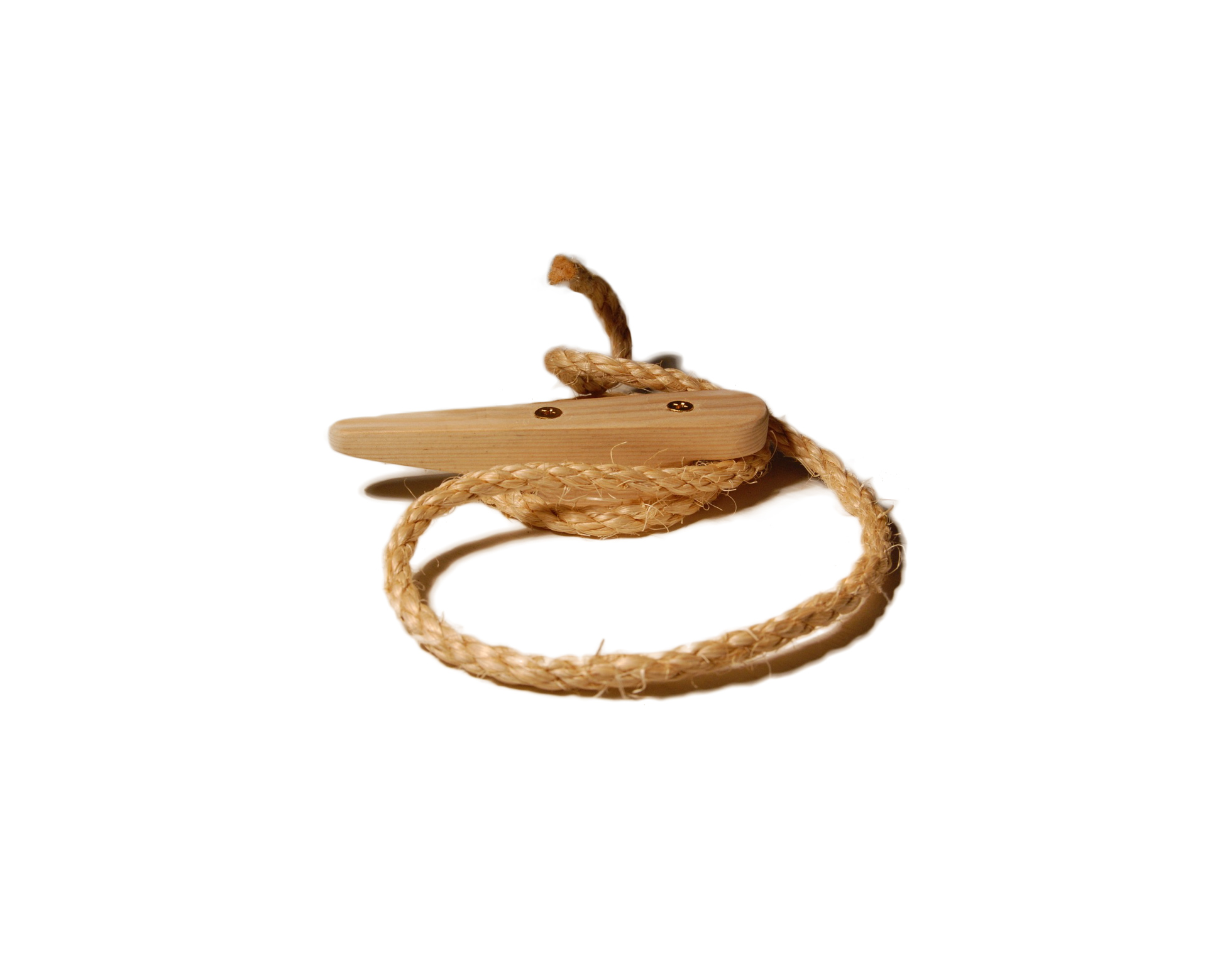
Lawnmower Starter Rope Replacement

The other week when I pulled the rope on the mower, the rope broke off. Fortunately, the mower started and I just had the rest of the back yard to do. I finished it up, waited for the mower to cool and started the repair job.

My mower is a Yard Machines by MTD 22-inch side-discharge high-wheeler that I bought 15 years ago.
I have replaced the rope at least a couple of times. Here is how I do it.
For safety, disconnect the sparkplug wire from the sparkplug by pulling on the rubber cover.
There are two screws that retain the top cover. The screwdriver is pointing to one of them, the other is on located on the nearer side. Remove the screws with a Phillips screwdriver. Remove the top cover noting the index tab at the rear that engages the fuel tank. Also note the slot where cover allows the pull rope to pass through.

Using a 5/16″ socket, break the 3 hex bolts on the top of fuel tank ring loose (Figure 2). Using a 5/8″ socket, remove the bolt located under the fuel tank (Figure 3). Catch the spacer that is located between the engine block and the tab on the fuel tank. Remove the 3 screws on top. Lift and tilt the fuel tank toward the rear of the mower. It will remain attached by the fuel line.

The metal engine shroud is now exposed. Brush any dirt away from the lower end of the oil filler pipe where it enters the engine block. The oil filler will be loosened but not removed. But if it does fall out, cleaning will prevent dirt from falling into the crankcase.

There are two bolts on the front of the engine (Figure 4) and two bolts (Figure 5) on the back of the engine and the bolt that holds the oil filler. Using a 3/8″ socket, break loose the two front bolts and the two rear bolts. Use a 5/16″ socket to remove the bolt on the oil filler neck. Gently lift the oil filler neck to disengage the peg that holds the oil filler neck to the shroud. Twist oil filler neck slightly to get it out of the way.
Using the 3/8″ socket, remove the 2 screws each at the front and rear. Now lift straight up to remove the shroud and pull-start assemble. The starter will come out of the cup that is on top of the flywheel which engages the ratchet of the pull starter.

Looking at the underside of the shroud, you can see the pulley that the starter rope needs to run around. A tube inside the rim of the pulley (at approximately 9 o’clock position Figure 7) is where the starter rope needs to be attached. There is a small peg located opposite that will assist in winding the starter rope take-up spring.
Make sure the starter rope end is ready. Measure the new rope against the old and cut to length. Use a figure-8 knot to hold the rope in the handle. A new rope will have the nylon melted and may be ready to go. The melted portion should be no larger than the rope diameter (Figure 6). If it too large or you have trouble inserting it in the next step, heat the end of the rope with a flame or soldering iron. Use two pieces of wood to roll it into a pointed shape. Be Careful: Hot nylon can give you a nasty burn.


As you wind the pulley in a counter-clockwise direction, not that as you begin to feel tension on the spring, the ratchet levers are pushed out of the center area. These will engage the ridges in the cup that is on top of the flywheel. Continue winding the pulley 3 turns stopping when the tube is lined up with the hole in the shroud where the starter rope comes through. Push the pointed end of rope through the shroud and through the tube (Figure 8). Tie a figure-8 knot in the end. Slowly feed the rope into pulley as it unwinds. When the spring is relaxed, there should be slightly less rope exposed than it takes to reach the location on the mower handle. This slight bit of tension keeps the handle from drooping. If the rope is too long, stretch it out, re-tensioning the spring, draw in a few inches and tie a new knot.
Lower the shroud over the flywheel. Align the bolt holes, insert and finger tighten 1 bolt front and 1 bolt back. Verify the operation of starter ratchet. Release the blade-brake and pull the engine. Verify that the starter rope rewinds. Insert and finger tighten the remaining bolts on the block. Carefully, so that it does not pull out, position the peg of the oil-filler neck back in the hole in the shroud. Insert the bold and tighten. Tighten the 4 bolts front and rear.

Pass the handle and rope through the mounting ring of the fuel tank. Reposition the fuel tank on top of the shroud. Insert and finger tighten the 3 bolts on the ring. Under the fuel tank, insert the long, shouldered bolt through the tab on the fuel tank, then through the spacer (located above the end of the finger in Figure 9) , and finally into the engine block. Verify the adjustment and tighten all bolts.
Loosen the starter-rope guide on the handle to slip the rope into it. There should be a slight tension. Just enough to hold the handle in place. If the rope is too short, it will put tension on the spring and wear the ratchet. If too long, the handle will droop and snag shrubbery as you mow. Verify operation by pulling the engine with the blade brake off and allowing the starter rope to re-wind. If any of these checks are out, redo the steps above to make the appropriate adjustments. Reconnect the spark plug. Mower is ready to use again.